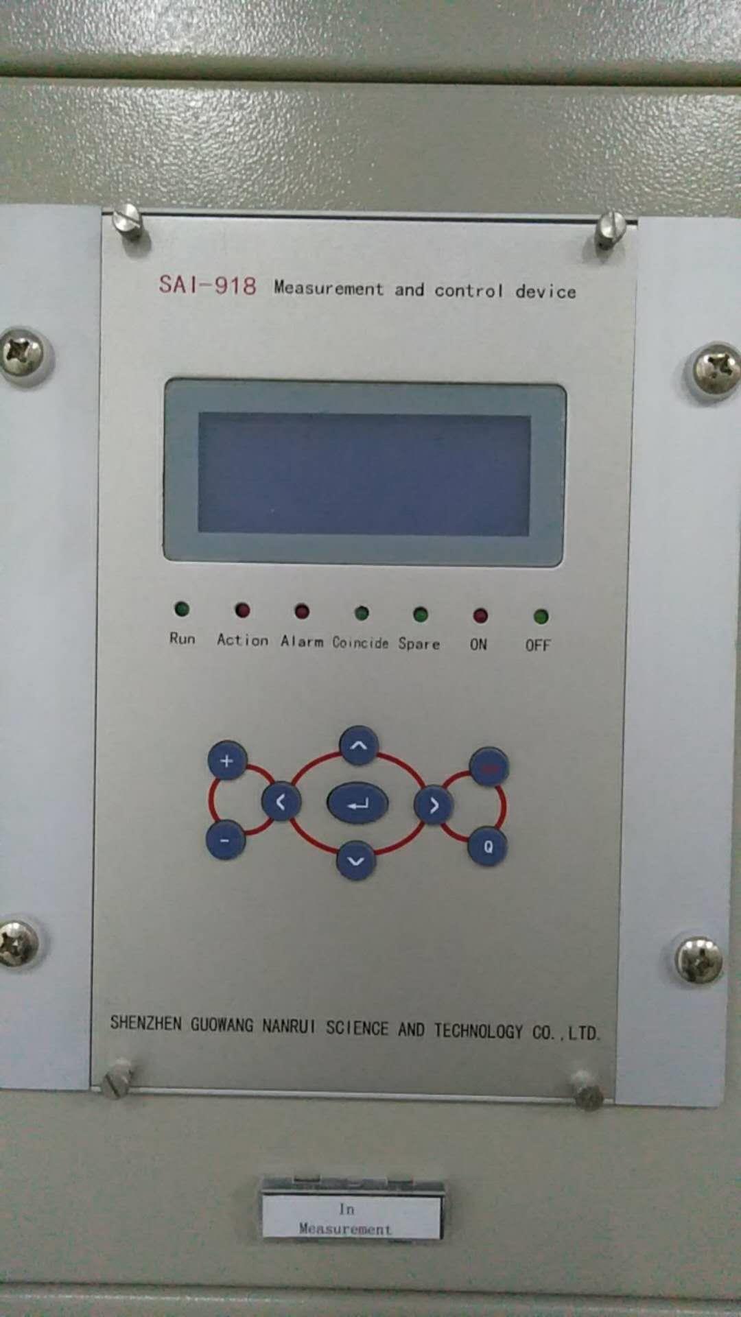
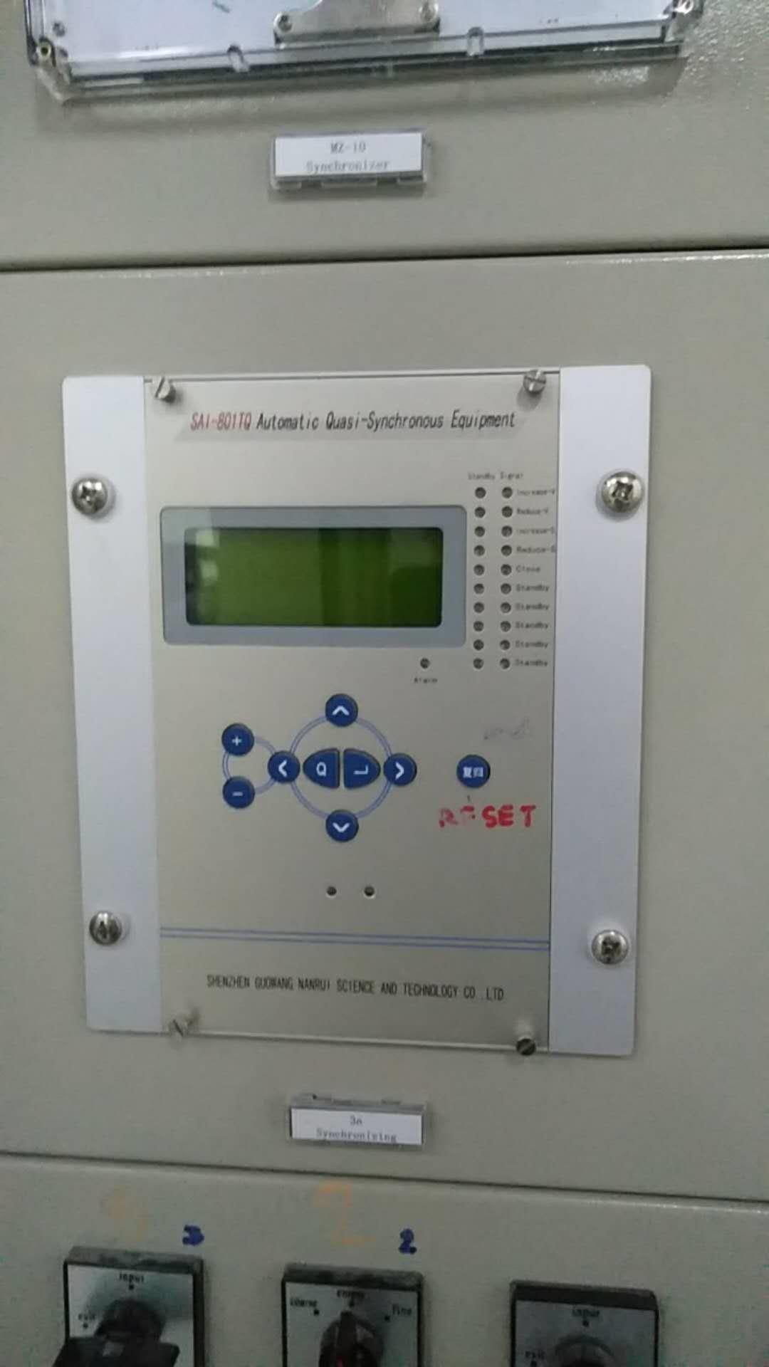
2.2 Main technical performance
Precise working range of 2.2.1 sampling circuit (10% error)
Voltage: 0.4 V ~ 120V
Current: 0.08In20In
2.2.2 contact capacity
Signal circuit contact current carrying capacity 400VA
Signal circuit contact fault arc capacity 60VA
2.2.3 tripping current
Breaker trip current 0.5A~4A (order indication)
The circuit breaker closing current 0.5A~4A (the order stated)
2.2.4 precision of various components
Current component: <5%
Voltage components: <5%
Time element: 0s-1s, the error is not more than 40ms;
1s above, the error is not more than < + 2.5%;
Frequency deviation: <0.02Hz

AC measurement
A group of three-phase current, three-phase voltage and zero sequence voltage, power, frequency, power, power factor
Switch input
11 way switch input, can be the whole set of non electric power for "trip" or "alarm", the first 4 non electricity can be arbitrarily set trip exit
Switch output
8 way switch contact output, the 4 switch jump closing control
control loop
Jump control circuit, circuit breaker hand jump, hand closing operation and hop position indication

2.3.2 medium strengthUnder normal test conditions, the device can withstand the frequency of 50Hz, voltage 2000V lasted 1 minutes of power frequency voltage withstand test without breakdown flashover and component damage. During the test, the other circuit is connected to the ground with the other circuit when the voltage is applied.
2.3.3 impulse voltageIn the normal test atmospheric conditions, device power input circuit, the AC input circuit, output contact circuit and loop between, can withstand the 50s of the standard lightning wave short-time impulse voltage test, open test voltage 5kV.
2.3.4 resistance to damp heat resistance
The device can withstand the damp heat test specified in the twenty-first chapter of the GB7261. The highest temperature test + 40 DEG C, maximum relative humidity of 95%, the test time for 48 hours, each cycle lasted 24 hours of cyclic damp heat test, at the end of the test within 2 hours before according to the requirement 2.3.1, measure the circuits between the conductive circuit foreign Lufei charged metal part and the shell, electrical contact between the insulation resistance is not less than 1.5m ohm, medium compressive strength of not less than 75% of the 2.3.2 provisions of the dielectric strength test voltage amplitude.
It is proposed that the turning point in the component current Ir0 is set to 1 times the rated current of the high voltage side to ensure that the turn to turn short circuit in the braking current is less than the rated current Ie Ir, there is no braking effect.
Differential current threshold criterion should not be too small, it is recommended to take Icd = (0.3 ~ 0.5) Ie.
The setting of the ratio braking coefficient can be carried out according to the following formula:
Kcd = Kk (Ktx / Fwc + Fph)
Among them, Kk is the reliable coefficient, take 1.3 ~ 1.5
Ktx for the same type coefficient, take 1
Fwc for the current transformer to allow the error, take 0.1
The Fph for the current caused by current transformer unbalanced relative error is 0.05.
Ratio braking coefficient Kcd recommended range of 0.3 to 0.7.Id =∣
Two technical parameter
2.1 Rated parameters
2.1.1Rated DC voltage: 220V or 110V (order indicated)
2.1.2 Rated AC data:
a) Phase voltage V
-/gjigcb/-

